Hi Tom,
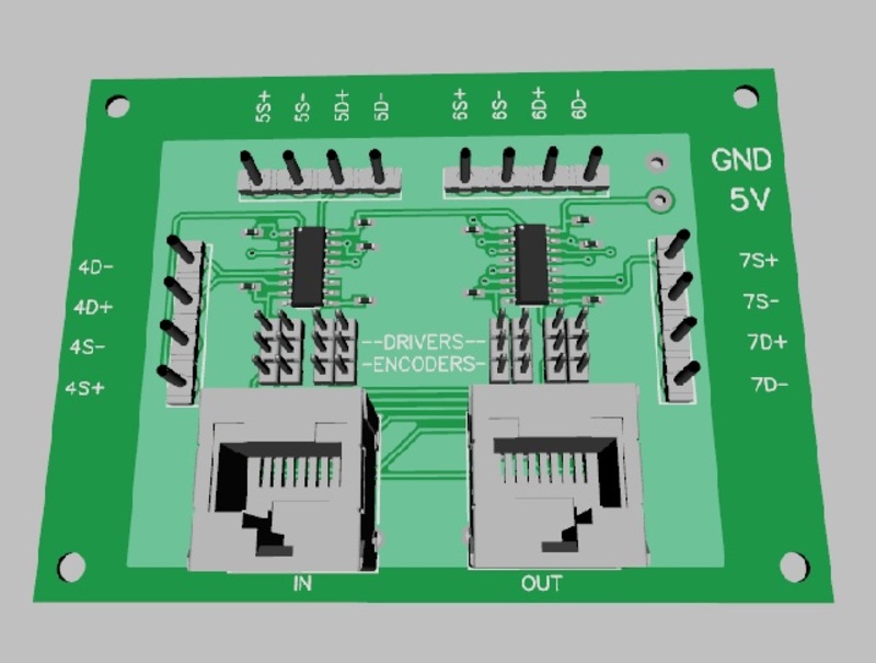
thanks for the comments. There is a 0.1uF ceramic SMD cap at each chip, it's just the 3D render picked a resistor file instead of a capacitor one. I keep meaning to add something a bit bigger at the power input, which I'll do once I decide on what type of connector to use, as I'd like something that is polarised so it doesn't end up being plugged in the wrong way around.
For the milling machine this is going into, I had considered doing something that would not involve a Kanalog, but if this machine does what I'd like, I'd probably want to upgrade it to servos at some point, so using the Kanalog makes sense.
But it did get me thinking a bit about a more universal board, and what it would actually need to provide.
Take this machine as an example, I'd need 3 differential step/dirs (ideally 4 to allow for 4th axis), a 0-10V output for the spindle drive, 2 encoder inputs (one for an MPG, one for spindle feedback), and then I think around 9 24V inputs and 6 24V outputs (I still need to go through the wiring diagrams to work out the exact requirements).
Then I'd like to use a pendant, so I'd need an extra 4 inputs for the axis switch, 3 or 4 inputs for the step size switch, and an output for the pendant active light.
I'd like to add physical buttons for cycle start, and feed hold, so another 2 inputs, and I'd like them back lit appropriately so another couple outputs. Then either two more encoder inputs, or two analogue inputs for SSO, and FRO dials.
From that, I'd be looking at a total of about 18/19 inputs, 9 outputs, 4 step/dir outputs, 2 encoder inputs, and either 2 more encoder inputs or 2 analog inputs.
However, I'm sure most people you ask will come up with totally different requirements.
As for the RJ45 suggestion, I can see the appeal, but it's not an option I'd personally prefer.
Moray